
Why Choose a Foot Pedal Valve for Industrial Use?
In industrial environments, operators often need both hands for loading, positioning, or monitoring equipment. A Foot Pedal Valve offers a practical way to control pneumatic or hydraulic flow while keeping those hands available. Pressing the pedal can start, stop, or redirect air pressure with a simple, deliberate movement. This matters beside assembly stations, stamping equipment, clamps, and material-handling fixtures.
The value becomes clearer during repetitive work. A well-positioned pedal can reduce unnecessary reaching and help maintain a steady operating rhythm. However, convenience should never replace careful engineering. Selection depends on pressure range, port size, valve function, cycle frequency, and the working environment. Dust, oil, moisture, and accidental contact can affect performance. Small details matter.
It is not magic.
Experienced maintenance teams usually check the manufacturer’s technical data before installation. They also consider guarding, return mechanisms, emergency isolation, and compatibility with existing controls. A pedal that feels comfortable during a short test may become tiring after several hundred cycles. That point is easy to overlook. Foot clearance, slip resistance, and mounting stability deserve equal attention.
A reliable Foot Pedal Valve should provide consistent actuation and predictable service life. Still, no component works safely in isolation. Proper installation, routine inspection, and operator training remain essential. This guide examines why industrial users choose foot pedal control, where it performs well, and which limitations should influence the final decision. Some applications may need a hand control or integrated safety system instead. That honest comparison supports better purchasing decisions and more dependable production.
What Is a Foot Pedal Valve?
Why Choose a Foot Pedal Valve for Industrial Use?
What Is a Foot Pedal Valve?
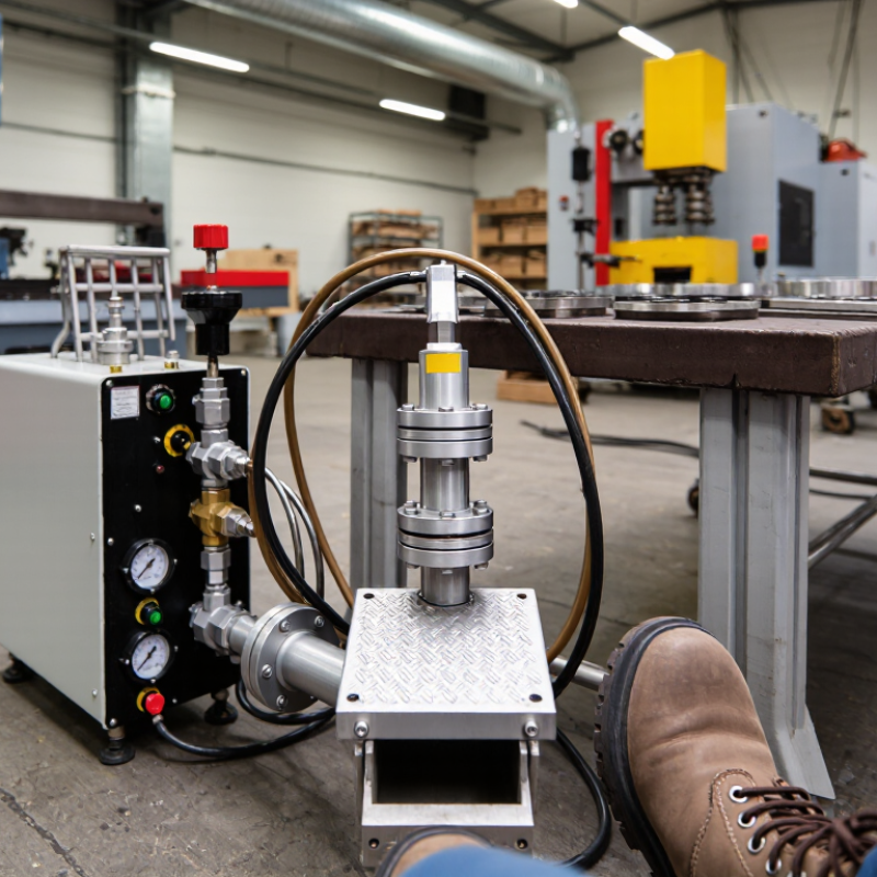
A foot pedal valve is a manually operated pneumatic directional valve. It controls compressed air without requiring the operator’s hands. Pressing the pedal shifts an internal spool, sending air to a cylinder, clamp, or actuator. Releasing the pedal may return the valve by spring force, depending on its design. Common configurations include 3/2 and 5/2 valves.
In a real workstation, this can improve workflow. An operator may hold a workpiece with both hands while tapping the pedal with a safety shoe. The response is simple and easy to feel. However, the pedal must resist accidental activation. ISO 4414 stresses safe pneumatic system design, including controlled energy release and reliable components. A guard or recessed mounting position is often sensible, although it is sometimes overlooked.
The U.S. Bureau of Labor Statistics reported about 2.6 million nonfatal workplace injuries and illnesses in private industry during 2023. This figure does not prove that foot valves prevent injuries. It does show why control placement deserves careful review. OSHA guidance for machine controls also emphasizes preventing unintended operation. A foot valve can support this goal, but poor positioning can create a hazard. That uncomfortable detail matters.
Before selection, check operating pressure, port size, return action, pedal force, and cycle frequency. ISO 1219-1 symbols can help engineers document the pneumatic function clearly. In practice, dirt, wet floors, and worn springs may reduce confidence. Regular inspection remains necessary. Simplicity is useful, but it is not the same as safety.
Why Choose a Foot Pedal Valve for Industrial Use? - What Is a Foot Pedal Valve?
| Data Dimension | Typical Industrial Information | Why It Matters |
|---|---|---|
| Definition | A foot pedal valve is a manually operated directional control valve activated by pressing a pedal with the operator’s foot. | It allows the operator to control pneumatic or hydraulic motion while keeping both hands available for positioning and handling workpieces. |
| Common valve functions | Frequently used configurations include 3/2, 4/2, and 5/2 directional valves. The exact function depends on the actuator and circuit design. | The number of ports and positions determines how air or fluid is routed to extend, retract, start, stop, or switch an actuator. |
| Typical operating medium | Most foot pedal valves are used with compressed air. Hydraulic versions are available for applications requiring higher force and pressure. | Selecting a valve designed for the correct medium helps prevent leakage, seal damage, contamination, and unsafe operation. |
| Actuation method | The valve is operated by foot pressure through a treadle or pedal. Some models use spring return, maintained position, or guarded actuation. | The return method affects whether the actuator stops when the pedal is released or remains in its selected state. |
| Port sizes | Common connection sizes range from approximately 1/8 inch to 1/2 inch in pneumatic equipment, although larger or smaller sizes are also available. | Port size influences flow capacity, tubing compatibility, pressure drop, and the speed of the connected actuator. |
| Pressure capability | Pneumatic models are commonly designed for compressed-air systems around 0.2–0.8 MPa, or approximately 2–8 bar, depending on construction and specifications. | The valve’s rated pressure must meet or exceed the system’s maximum working pressure, including temporary peaks. |
| Flow capacity | Flow capacity is specified by the manufacturer using a flow coefficient, standard liters per minute, or another recognized rating. It varies with port size and internal design. | Adequate flow capacity helps the cylinder or actuator reach the required operating speed without excessive pressure loss. |
| Valve body materials | Typical materials include anodized aluminum, zinc alloy, stainless steel, or engineered polymers. Internal seals are commonly made from elastomeric materials selected for the medium and temperature. | Material selection affects corrosion resistance, mechanical durability, weight, chemical compatibility, and service life. |
| Temperature range | Many general-purpose pneumatic valves operate within an approximate range of −5°C to 50°C, while specialized designs may support wider temperatures. | Ambient temperature, compressed-air temperature, and seal material all influence reliable operation. |
| Operator ergonomics | A foot pedal can be positioned at floor level and operated without removing the hands from the work area. | This can reduce unnecessary hand movement and support faster, more consistent operation in repetitive tasks. |
| Safety features | Available safety options may include pedal guards, protective covers, spring return, locking mechanisms, and emergency-release arrangements. | A guarded or spring-return pedal can help reduce unintended actuation, but it does not replace a complete machine risk assessment and safeguarding system. |
| Typical applications | Common uses include pneumatic presses, clamping fixtures, punching equipment, assembly stations, cutting tools, packaging machinery, and workholding systems. | These applications benefit when the operator must coordinate manual part placement with actuator control. |
| Installation requirements | The valve should be mounted securely on a stable surface, connected with correctly sized tubing, and installed with appropriate air preparation and exhaust arrangements. | Correct installation reduces vibration, leakage, contamination, accidental movement, and inconsistent actuator performance. |
| Maintenance needs | Routine checks should cover pedal movement, mounting hardware, tubing, fittings, seals, contamination, leakage, and return action. | Regular inspection helps identify wear or malfunction before it causes downtime or creates a safety hazard. |
| Main advantages | Hands-free control, simple mechanical operation, quick response, straightforward installation, and suitability for repetitive industrial cycles. | These characteristics can improve workflow efficiency where manual control is preferred over an electrical switch or fully automated control. |
| Selection checklist | Confirm the medium, valve function, number of positions, port size, pressure rating, flow requirement, temperature range, mounting method, pedal style, and safety requirements. | Matching these parameters to the machine circuit is essential for dependable performance and safe operation. |
Note: Specifications such as pressure, temperature, flow capacity, materials, and connection sizes vary by valve design. Always verify the technical data for the selected configuration before installation.